
Quick Start
This guide walks you through building your first hardware project on WhispBuild, from scratch.
What You Need
- A WhispBuild-supported device (this tutorial uses the Valon-I3 Smart Car)
- A USB cable
- Chrome or Edge browser (Web Serial API support required)
Part 1: Ready to Use — Valon-I3 Smart Car
If you have no hardware or programming background, we recommend starting with the Valon-I3 Smart Car. It comes with an ultrasonic sensor, servo, line-tracking sensors, IR obstacle sensors, motors, RGB LEDs, a buzzer, and more — all built in. No extra hardware to buy, no wiring to do, no technical knowledge required.
Step 1: Sign Up and Log In
- Open your browser and go to apps.whispbuild.com
- Click Log In and sign up with your phone number or email
- After logging in, you'll see the "My Projects" page
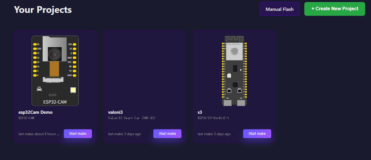
Step 2: Create a Project
- Click the "+ New Project" button
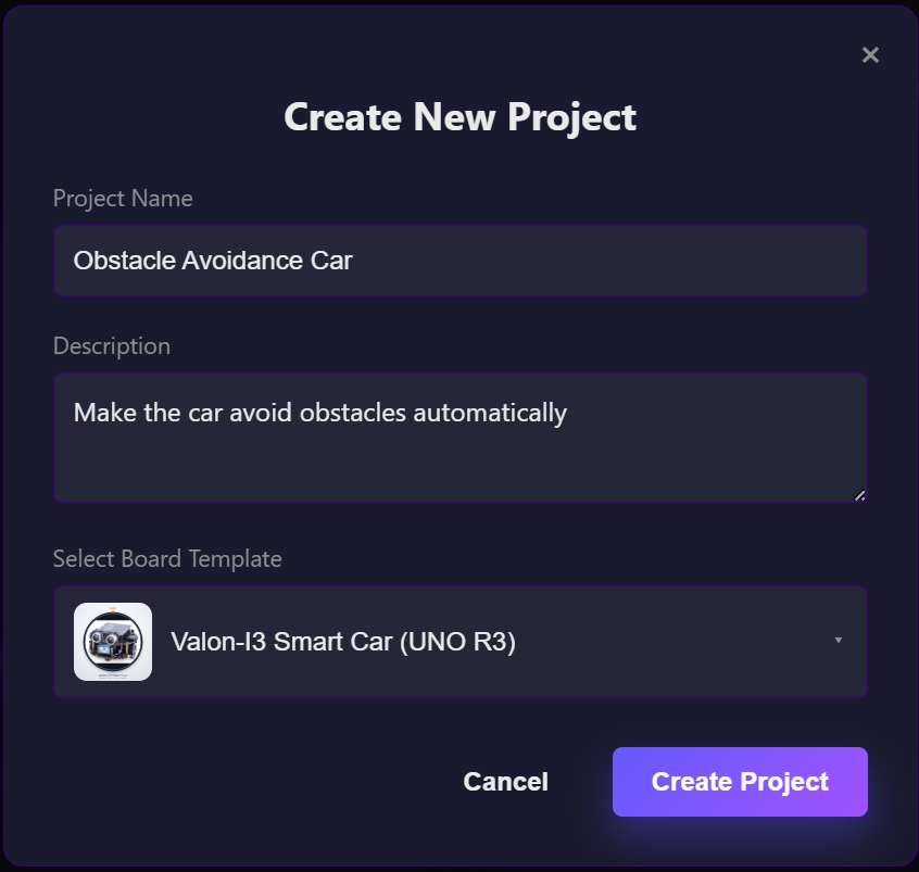
- Fill in the form:
- Project name: e.g., "Obstacle Avoidance Car"
- Description: e.g., "Make the car avoid obstacles automatically"
- Select board: Choose Valon-I3 Smart Car (UNO R3)
- Click "Create Project"
Step 3: Open the Workspace and Start Chatting
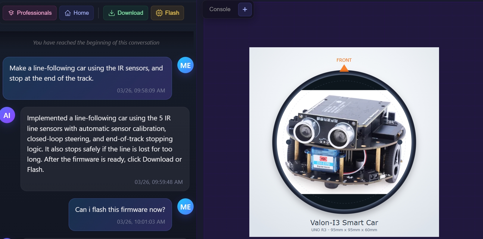
Click the "Start Building" button on the project card to enter the workspace.
Since all hardware modules on the Valon-I3 are pre-configured, you don't need to add modules or connect any pins — just type your idea directly in the AI chat panel on the left.
For example:
Drive the car forward for 3 seconds, then spin in a circle.Use the ultrasonic sensor to detect obstacles ahead. When an obstacle is found, stop, scan left and right with the servo to find a clear direction, then turn and keep going.Make the car follow a black line on the ground.Play a melody on the buzzer while the RGB LEDs change color to the beat.Press Enter to send. The AI will generate complete firmware code and compile it in the cloud.
Step 4: Flash the Car
Once the build succeeds:
- Connect the car to your computer with a USB cable
- Click the "Flash" button in the top toolbar
- In the dialog, click "Connect Serial Port"
- Your browser will show a serial port picker — select the port for your car
- Once connected, click "Start Flashing"
- Wait for the progress bar to finish — you'll see a "Firmware flashed successfully" message
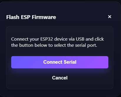
Note: Online flashing requires Chrome or Edge. Safari and Firefox do not support the Web Serial API.
Step 5: Observe and Debug
After flashing, unplug the USB cable, turn on the car's power switch, and watch it run.
If the car doesn't behave as expected, describe the problem to the AI:
The car didn't stop when it hit an obstacle — it just crashed into it. Can you check the ultrasonic distance threshold?Or connect the serial console to check the logs:
- Click the "Console" button on the right panel
- Click "Connect", select baud rate
115200, then click "Connect" - Read the device logs and paste them to the AI for analysis
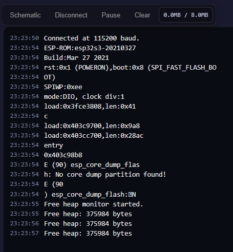
The AI will analyze the problem, regenerate the firmware, and you just click "Flash" again.
This cycle — describe your idea, compile, flash, observe, report issues — is how you develop on WhispBuild.
Part 2: Advanced — General Development Boards (Canvas Mode)
If you have some hardware experience and want to use boards like ESP32 or Arduino with your own sensor modules, you can use Canvas Mode.
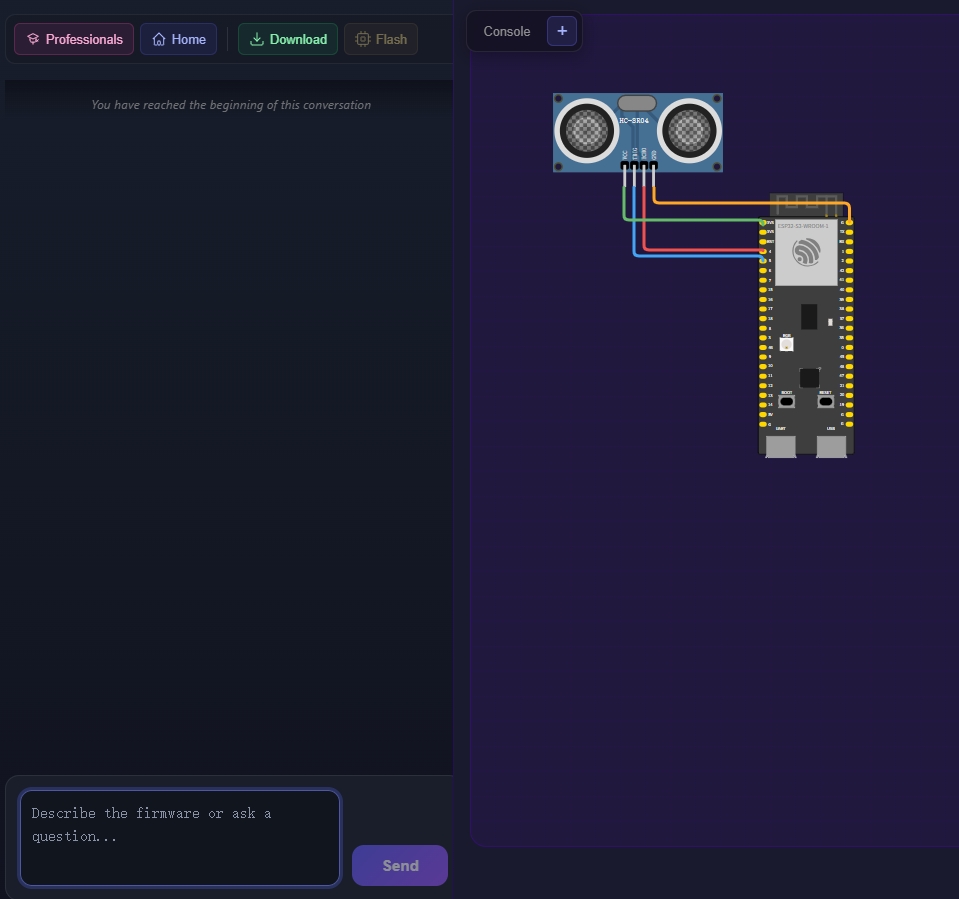
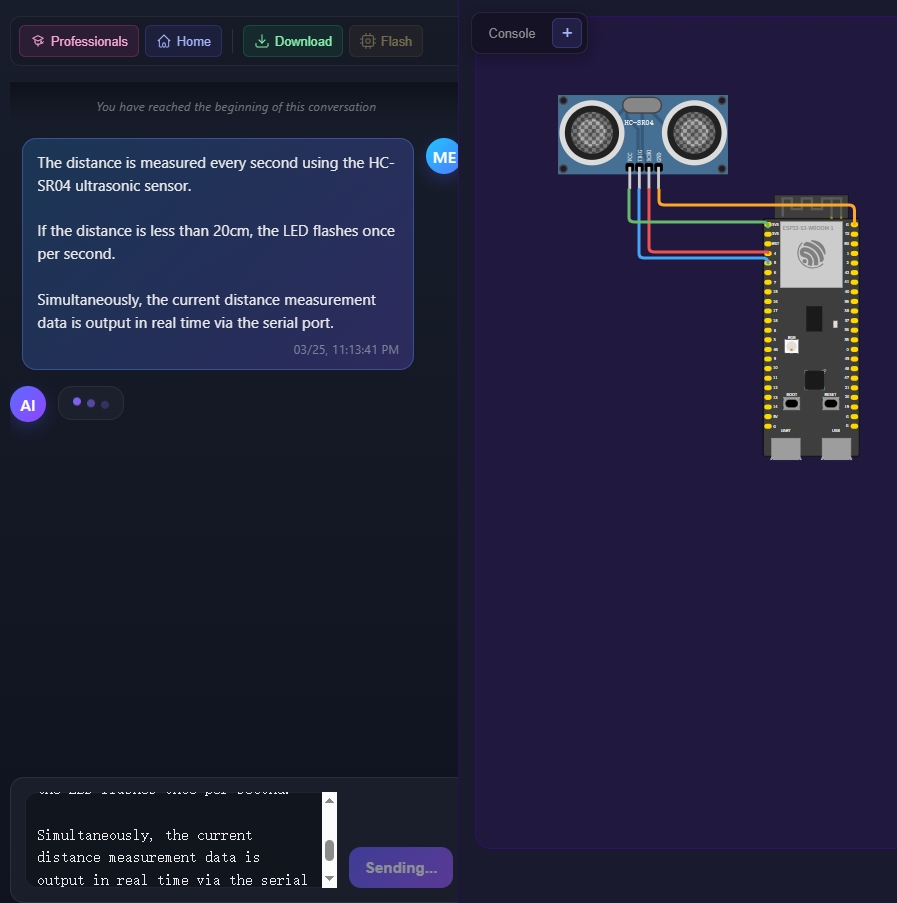
The following example uses an ESP32-DevKitC with an HC-SR04 ultrasonic sensor.
Step 1: Create a Project and Open the Workspace
- Click "+ New Project" and select
ESP32 DevKit V1as the board - Click "Create Project", then click "Start Building" to enter the workspace
You'll see a split-screen layout: the AI chat panel on the left, and the hardware wiring canvas on the right.
Step 2: Add Hardware Modules
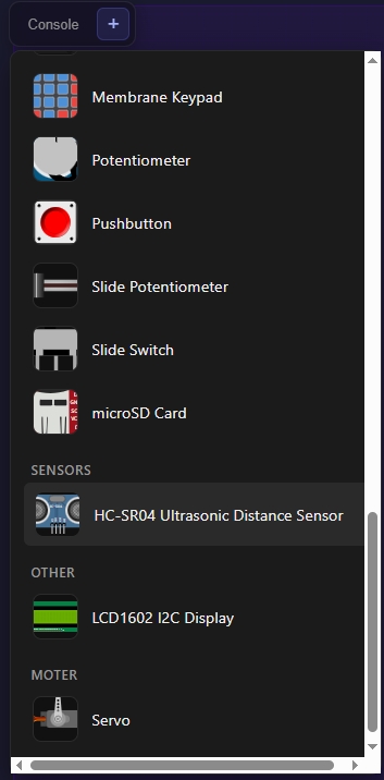
- Click the "+" button at the top-left of the canvas to open the module picker
- Type a module name in the search box, e.g.,
HC-SR04 - Drag the module from the panel onto the canvas
Step 3: Connect Pins
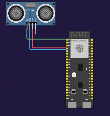
- Hover over a pin on the development board (you'll see the pin name)
- Click the pin to start drawing a wire
- Click the corresponding pin on the module to complete the connection
Make sure the wiring on the canvas matches your actual hardware connections.
Tips:
Double-click a wire to delete it. Select a module and press Delete to remove it.
Step 4: Describe Your Idea
Type your request in plain language in the chat panel:
Write firmware that measures distance with the HC-SR04 ultrasonic sensor every second.
If the distance is less than 20cm, blink the LED once per second.
Also print the distance readings to the serial output.
Press Enter to send. The AI will use your canvas wiring and description to generate firmware code and compile it in the cloud.
Step 5: Flash and Debug
Once the build succeeds, the flashing and debugging process is the same as Part 1:
- Connect the board via USB, click "Flash" to upload the firmware
- Click "Console" → "Connect" to view serial output
- If something is wrong, describe the problem or paste logs to the AI, then flash again
Tips:
Click "Pause" to freeze the log output. Click "Clear" to clear the log. Click "Schematic" to switch back to the canvas.
FAQ
Browser says serial is not supported?
Make sure you are using Chrome 87+ or Edge 87+. Safari and Firefox do not support the Web Serial API.
Can't find the device after clicking Flash?
- Check that your USB cable is a data cable (not a charging-only cable)
- Try a different USB port
- Windows users may need to install the CP2102 driver
Can I connect multiple devices at once?
Currently, you can only connect one device at a time for flashing or viewing logs.
Next Steps
Congratulations on completing your first project! Here's what you can try next:
- More complex projects: add an OLED display, WiFi connectivity, Bluetooth control, and more
- Switch to Pro Mode (click the "Professionals" button at the top of the chat panel) for more control
If you have any questions, just ask the AI in the chat — it's your hardware development partner.